Magnetic stripe reader circuit

by

L. Padilla

Requirements

To read magnetic stripes with this design you will need a magnetic head, two transistors, a few resistors and capacitors, a 12 Volts DC power supply, a computer (with a C compiler) to decode the data and some soldering skills. A voltmeter and an oscilloscope are highly advisable while adjusting and testing the circuit. Maybe you can substitute the scope with a sound card if it can digitalize fast enough.

The magnetic head has to be chosen such that the size of the track matches that of the magnetic stripe. I found that the size of the track of a normal mono audio cassette player is a little bit smaller than required but it works well. Using a stereo audio head is not recommended unless you want to read two tracks at a time, but I have not checked whether the separation of the audio tracks is the same than that of the data tracks.

Circuit description

The weak signal from the magnetic head has to be amplified in order to drive an input port of the computer. For that reason you will need a circuit like the one in the figure bellow (or a similar one) which is basically an amplifier. The transistor Q1 acts like a preamplifier, raising the weak head signal, under 1 mV, to the level of tenths of volts. As a preamplifier, it has a low noise factor; this is achieved through operating the transistor at low current (under 1 mA) and low voltage (under 2 V).

The transistor Q2 acts like an amplifier and a driver for the input port of the computer. For that reason its output is connected directly, without any capacitor, to the input port of the computer. Therefore the DC voltage level of the transistor has to be adjusted to match the specifications of the port you are using. Both transistors, Q1 and Q2, have to be normal silicon bipolar general purpose NPN transistors. The value of the electronic components is not critical, specially for capacitors. You can choose from what you already have, those which are closer to the ones in the drawing.

This circuit is designed to work with a 12 V DC power supply. You can use another one, but then you will have to change the value of the resistors to keep the working point of the transistors in the same place. You can obtain +12 V DC from the power supply of your PC, which also have +5 V DC. The power consumption of this circuit should be around 60 mW. If your power supply is stabilized (that is the case of the power supply of the computer) then you may remove the capacitor C7, otherwise you should use a value as big as possible. Pay attention on the voltage the capacitor is rated, it should be no less than 16 V. You should also pay attention on the polarity of this and the other capacitors. The terminal rated "-" must be connected to ground or closer to ground than the other terminal. See scheme for details.

MagAmp

Adjusting the circuit

You can make the circuit as it is drawn in the figure and it should work. However, for optimum performance, it is advisable that R2 and R6 would be variable resistors of value around 20 kOhm and 2 kOhm respectively. Initially place the cursor of the resistors in the middle position, that is, to get around 10 kOhm and 1 kOhm respectively. Then, while swiping a magnetic stripe card, change slowly the value of R2 until you get a square wave signal with maximum amplitude and minimum noise. This can be easily done if you have an oscilloscope (or a sound card acting like one), if you have not, then you can connect a speaker to the output and try to do it by hearing, although its results may be unpredictable.

Once you have set R2 for optimum performance, you have to adjust R6 to the proper value. Use the voltmeter to measure the DC voltage at the output of the circuit. Then, NOT swiping any card, change slowly the value of R6 until the DC level of the output is somewhere between 4.0 and 4.5 Volts. This assumes that the input port of the computer you are going to use works with TTL levels, that is, 0 and +5 V. The ideal voltage of the output would be +5 V, but you have to take into account that while swiping a card the output of the amplifier is going to exceed this voltage. That is the reason why you should set a lower value than +5 V for the output of the amplifier when not reading any card.

Advices

The Zener diode Z1 is used to protect the port of the computer against an excessive raise of the voltage. Its inverse breakdown voltage should be between 5.5 and 6.5 Volts. If you cannot get a Zener diode with that characteristic, you can get the same effect with normal diodes. A normal silicon diode drops by around 0.6 V the voltage of a signal in the direct direction, therefore if you put 10 normal silicon diodes in series they behave in direct direction as a Zener diode with inverse breakdown voltage of 6 V in inverse direction. You can also use a combination of both types. If you have a Zener diode of 4 V you should put 3 normal diodes in series with the Zener diode to get a breakdown voltage of about 5.8 V. Remember, Zener diode has to be put in inverse direction and normal diodes in direct direction. If you still cannot get this protection with diodes, then you should set the DC voltage of the circuit, when not reading, to a lower value, for example, between 3.0 and 3.5 Volts. This gives you an extra margin of protection and still would drive correctly the port of the computer.

You should pay attention to correctly ground every part of the circuit, especially to high frequencies, that is the reason for the capacitors C4 and C6. Grounding is very important to get ride of noise. The metallic shielding of the magnetic head should be grounded. You could also put the circuit inside a metallic case and ground it. Connect the magnetic head to the circuit with a cable as short as possible to avoid noise pick up. You have to take into account that the vicinity of the computer is a (electrically) very noisy environment. You may even notice that the noise pick up is considerably reduced if you are also grounded while swiping the card.

Mechanics of the reader

If you want to read magnetic stripes successfully, you should use a mechanical device to swipe cards stably and reliably. You can either swipe the card over the head or the head over the card. I chose the second method.

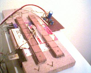
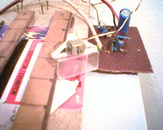
In this case you should attach the magnetic head (with the sensitive side downwards) to a piece of plastic, wood or something with a regular shape and a smooth surface. Then fix two strips (one at each side of the head) on a board as a rail in which the magnetic head can only move forward and backward (smoothly). Be aware to leave enough space between the board and the strips in order to introduce the card which is going to be read. Once you fix the card on the board, with its magnetic stripe running parallel to the strips, you can swipe the head along the card easily. Now you only have to move in small steps the position of the card until you find the track to be read. You know that the track is caught when the signal from the amplifier is a perfect square wave with maximum amplitude and minimum noise. As long as the majority of the cards follows the ISO standards, I suggest you to make some marks on the reader to sign the position of the tracks. So you don't have to repeat the whole process each time you want to read a card.

It may be not the most simple or efficient reader mechanics, but it allows you to read virtually any track of any card or document, i.e. it is not restricted to standard size cards or standard position tracks. See photos below to get an impression of the reader (click on images to enlarge). I apologize for the bad quality, I wasn't able to get a better digital camera (I used a cheap webcam).

MagRead MagHead

Lately I've been using a very simple method to swipe cards which does not require a special board with strips fixed on it (rails). Simply put the card on your computer table and use the keyboard as rail for the magnetic head, i.e. it's like the method above but using a normal table and just one rail, one side of your computer keyboard. Put two cards one at each side of the card to be read (all three cards should have the same thickness) to help the magnetic head to move smoothly (you still need to attach the head to something suited for swiping). Be sure the magnetic stripe of the auxiliary cards do not interfere with the magnetic stripe to be read, i.e. the magnetic head is not going to swipe them as well. The only problem is to keep the magnetic stripe aligned with the keyboard, find your our method to fix this.

Using the software

The magnetic strip reader should be connected to the joystick port (output of the reader to pin 2 and ground to pin 4) or to the parallel port (output of the reader to pin 15 and ground to pin 18) of a PC if you are going to use the software provided in these pages. I found a better performance using the parallel port, and so, that is the default port. You can use any PC, there is no need for a fast powerful PC. Compile the source code optimizing for speed. If you don't use Turbo C++ v1.01, you may need to change a little bit the code, mainly headers and function names.

When you run the program it waits for activity in the input port, that is, a card swipe. When the activity stops, the program starts decoding the bits, forming bytes and checking parity and LRC. The input level of the port is high with or without the reader connected to it. When you swipe the card, some of the flux reversals create a negative current which drops the output of the reader under +0.4 V, and thus turning the input port from high to low state. The opposite flux reversals increase the output of the reader over +5 V, and thus turning the input port from low to high state again. This is the activity the program detects.

The program has two input arguments, the type and the number of leading and trailing clocking bits of the track to be read. There are four valid tracks, the three standard tracks plus one experimental. The experimental track does not check for parity or LRC and it decodes the bits in a slightly different manner than the standard: 0s are the same, but 1s are only one short flux reversal, and not two short consecutive reversals like in the standard. I found this non standard coding of bits in at least one card (photocopier card). The number of clocking bits depends on the card you are reading. If you don't know which number to use, type a 1, then the program will use the default number based on the track type (and on my experience). Once you have read the track, on the screen will appear the bits, and then you can count the number of leading and trailing clocking bits. Next time you read that card use the lower of these two numbers. Using the right number of clocking bits will improve the success rate in card decoding.

The program will also show other information on the screen, as the swipe time, the decoded bytes and some data on the quality of the reading. I found that the optimum swipe time is between 0.2 and 0.4 seconds. The best swipe time for standard size low density tracks is 0.20 - 0.25 s and for high density tracks is 0.30 - 0.35 s. The swipe has to be as smooth and uniform as possible, otherwise the program will wrongly interpret 0s as 1s and vice versa. A good quality swipe will be characterized by small sigmas and by threshold1 > threshold2 in the information on the screen.

There is some code in the source (commented out by default) which dumps to the screen the raw data read. This option is useful when you are reading non standard tracks. The raw data can be analyzed with data utilities to find out the coding scheme. In general you should get familiar with the source code to know how it works. This would help you to interpret the information shown on the screen after a swipe and would let you modify the code to fit your particular requirements.

To conclude, here is the output of the program after reading a standard IATA track (Lufthansa boarding pass):


Bad clocking bits parameter. Using defaults.
Reading track 1.
Swipe time: 0.33 s.
Time unit: 5.7e-06 s.
Initial duration (sigma) of bits in time units:
0LO:  96.0 (11.0), 1LO:  48.0 ( 5.5)
0HI: 116.7 (12.1), 1HI:  58.4 ( 6.1)
Initial thresholds LO:  73.9,  59.0,  64.0
Initial thresholds HI:  92.5,  70.5,  77.8
000000000000000000000000000000000000000000000000000101000101101110110010010011
010000111011011100001100100110011010000101100000010010101111010100001000100101
000000110110110000111100001100100111001010001101000110101000011111100100110101
010111100101011001110000001000000100000010000001000000100000010001101011001000
000010000001000000100000011111100011010000000000000000000000000000000000000000
00000000000000000000000000000000000000000000000000000000000
Mean duration (sigma) of bits in time units:
0LO:  95.2 ( 8.9), 1LO:  47.9 ( 4.3)
0HI: 115.4 (10.4), 1HI:  59.8 ( 5.6)
Final thresholds LO:  77.4,  56.6,  63.4
Final thresholds HI:  94.7,  71.0,  79.3
Start sentinel found.
%VFRAMADLH 4702 MPADILLA/L.        8F    ?
End sentinel found.
LRC OK.

Enhancements

The main problem I found with this device is that it introduces an asymmetry in the bits read, i.e. the output is not a symmetric square ware, bits at low level are shorter than bits at high level. The reason for this is that the default state of the reader is high level, when a magnetic flux reversal induces high level the output is at high level 100% of the duration of the bit. However when a flux reversal induces low level it takes some time to change from default high level, say 4 volts, to the point where the port switches from high to low state, say 2 volts. It happens a similar thing with the tail of the bit, the port switches from low to high state before the bit has ended. The net effect is that low bits are shorter (the port is actually at low level only a fraction of the real bit duration) and high bits are longer because the time stolen to the low bits is added to the high bits (compare the values of 0LO and 1LO to 0HI and 1HI in the example above to see the difference). If the input signal were a perfect square wave with sharp vertical edges and the amplifier had a perfect response then this transition time from high to low state (and vice versa) would be negligible, but it is not the case.

At first I thought this effect was due to a problem in the design of the amplifier only, but then I realized there was an additional reason. The classic text Card-O-Rama: Magnetic Stripe Technology and Beyond states that the output of the magnetic head when swiping a magnetic track is a square wave, however this is not true. The actual output consists of a string of alternating positive and negative peaks, see this document (alternate location) for a detailed explanation including plots and see also my new reader page for some real data pictures (but take into account that these data are captured with a sound card and thus implicitly filtered with a narrow passband, hence the difference with the other document's plots). Therefore after a low level peak there is a time corresponding to the low level bit in which the reader goes into default state, that is, high level, and thus shortening the duration of the low level bit (and enlarging the neighbor high level bit).

Of course if you swipe a card quickly enough, specially if it is a high density track, the string of peaks would resemble a square wave, as you will see in my real data pictures (note the difference between the high and low density profiles). A similar thing would happen if the amplifier had poor response to high frequencies (like my design). Thus the effect can be compensated and is less prejudicial than one would first expect. To fix the other problem, the asymmetry, I took it into account in the software by measuring the duration of the bits using two different variables, one for low level bits and another one for high level bits (the LO and HI suffix of the variables as shown above). Therefore that's the reason why my reader really works, because both problems can be fixed. Nevertheless the reader (hardware and software) can still be improved in several ways, but I will not do it because I consider this project closed as long as I moved to my new and simpler reader. I will just give a few ideas from the theoretical point of view and it would be your work to test them, because they may have prejudicial side effects or require some tuning.

Obviously one the best improvements would be to use a better circuit, you may try one of the designs in my Magnetic stripe reader/writer page if you find them better than mine (you might still use my software). Assuming you choose my amplifier (mainly due to its simplicity, I presume) there are a few modifications which I believe would fix the asymmetry problem and give another advantages (more simplicity and protection of the PC port). The design would be simpler if we remove the Zener diode Z1 in parallel with the output, which is the only exotic component (well, no really so exotic :), apart from the magnetic head which is unavoidable, and put a normal diode in series with the output like this:

                    Amplifier output o-----|<|-----o PC port
                                         Diode D1
This gives a perfect protection of the PC port because the reverse breakdown voltage of a normal diode is several hundreds volts. Note that now the default high level state is maintained by the internal pull-up resistor of the port and no longer by the collector of transistor Q2. The DC current which formerly flowed from Q2's collector toward the PC port when a high state bit was read is now stopped by diode D1. This current is no longer needed because the port is already at high state due to the pull-up resistor. However when a low level bit is being read D1 let the current flow from the PC port to Q2's collector (and from there to ground) thus changing the state of the port from high to low state. This was the first enhancement I tried, but I did not publish it because it has a bad side effect: it worsens the asymmetry. This is due to the voltage drop of the diode (around 0.6 V for silicon diodes and about half of that for germanium type) which enlarges the gap that the low level flux reversal has to overcome to change the port from high to low state.

Now I have an idea about how to remove the asymmetry but I have not tried it, however you can test it. It's based on something which I had previously done in my old DAC-ADC design with success. In order to minimize the time needed for the low level flux reversal to switch the port from high to low state we must reduce the gap it has to overcome. We can do this by simply adjusting (not swiping any card) the resistance R6 so that the voltage output of the circuit is set at the minimum level which leave the PC port in high state. The best way to achieve it is to adjust R6 while running a program monitoring the status of the port (it can be a modified version of the program to use the reader), you will get to a point in which a little variation of R6 will change the status of the port. Leave R6 at this point but where the status of the port is stably high, to avoid false changes to low level when reading real data. With this adjustment when a negative flux reversal is read it will almost immediately change the status of the PC port from high to low state and therefore we record the real duration of the low level bit.

We can reduce the problem induced because the input signal (output from magnetic head) is not a square wave but a string of peaks by adding a couple of low pass RC filters (also known as integrators) so that peaks fall down slowly. You can do it by adding a couple of resistors (which we will call R9 and R10) in series with the circuit and raising the values of capacitors C4 and C6. It would be something like this (I only draw affected parts):

                 C3     R9                                    R10
          ... ---| |---\/\/\---+--- ...               ... ---\/\/\---+--- ...
                              _|_                                   _|_
                           C4 ___                                C6 ___
                               |                                     |
                              ...                                   ...
You have to choose R9 = R10 and C4 = C6 and so that R9(Ohms) * C4(Farads) ~ 0.001(seconds) which corresponds to a cut frequency of 1 kHz. This can be achieved with R9 = R10 = 1 kOhm and C4 = C6 = 1 uF, however I'm not sure about the optimum values so you can take R9 and R10 as variable resistors and do some fine tuning. You can test each setting reading real tracks and observing when you get better results: an increase in the read-out success rate and better numbers in the output: 0LO closer to 0HI, etc. Of course if you have an oscilloscope (or a sound card acting like one) is trivial to see whether the results are better or not.

Independently whether you try this hardware enhancements or not, in principle you can fix the two problems I mention above (asymmetry and peaks instead of square waves) by improving the software. Both problems are irrelevant if we measure the separation between peaks (this is the technique I used with my new reader) instead of measuring the duration of peaks or pseudo square waves (the technique used with this old reader). The problem here is that the PC port does not provide information about the relative level of the input signal, just whether it is above threshold or below. If we assume that the center of the peaks are located half way between consecutive changes of port status (this is a somewhat risky supposition) then we just have to measure the time between the center of the square waves the port is recording instead of measuring the time between status changes of the port level. This is rather easy to implement in my program, only a few modifications are required.

If you manage to remove both problems, either by hardware or by software improvements, you will be able to simplify the software because the different treatment of high and low level bits can be skipped, they can be managed as equivalents. This would make the software more robust because it increases the statistics of the bits (we approximately double it). In the end all is redundant in getting a more reliable reader which will require less swipes to read a card without errors. All these advices given in this final section had not been tried by me and you should experiment with them only if you like to play with electronics. If you just want to read cards with a minimal effort you should forget this device and try my new reader.


E-mail: padilla at domain "gae ucm es" (my PGP/GPG public key)
First version: 28-Jan-1997, last update: 5-Dec-2009
This link: http://www.gae.ucm.es/~padilla/extrawork/magamp.html
Color line
Back Go to the parent page: Magnetic stripe reader.